


Introduction
Wind load is a critical factor in the design of steel structures. Understanding how wind affects your structure ensures safety, stability, and compliance with engineering codes. Calculating wind load accurately is essential for engineers, architects, and construction professionals. In this guide, we will explain how to calculate wind load on steel structure, breaking down the steps clearly and providing practical examples.
Wind exerts pressure on structures depending on speed, shape, orientation, and location. Ignoring wind load can lead to structural failures, excessive deflections, or even catastrophic collapse. By following established codes and engineering principles, you can predict and manage these forces efficiently.
Understanding Wind Load
What is Wind Load?
Wind load is the force exerted by wind on a structure. It depends on the wind velocity, air density, and the area exposed to wind. Unlike static loads like dead or live loads, wind load is dynamic and varies with weather conditions. For steel structures, which often have large exposed surfaces, wind load is particularly significant.
Why It Matters for Steel Structures
Steel is strong but flexible, which makes it efficient in handling many types of loads. However, large steel frameworks, industrial sheds, or high-rise buildings can experience swaying or vibrations under wind pressure. Accurately calculating wind load ensures structural members are sized correctly, connections are robust, and safety factors are maintained.
Codes and Standards
Engineering codes provide formulas and guidelines for wind load calculations. Common standards include the ASCE 7 (American Society of Civil Engineers), Eurocode, and IS 875 Part 3 (Indian Standards). These codes consider wind speed maps, exposure categories, building height, and terrain roughness. Using these codes ensures calculations are reliable and legally compliant.
Steps to Calculate Wind Load on Steel Structure
Determine Basic Wind Speed
The first step is identifying the basic wind speed for the location. Basic wind speed is the maximum expected wind in a 50-year period, typically expressed in meters per second (m/s) or kilometers per hour (km/h).
Factors affecting wind speed include:
- Geographic location
- Elevation above sea level
- Historical weather records
Codes provide maps or tables to obtain the basic wind speed for a specific site.
Consider Exposure Category
Exposure category defines the terrain around the structure. Open fields, urban areas, and coastal zones experience different wind pressures.
- Exposure B: Urban areas with many buildings
- Exposure C: Open terrain with scattered obstructions
- Exposure D: Flat open terrain or coastal areas
Selecting the correct exposure category ensures the wind load calculation reflects real conditions.
Calculate Design Wind Pressure
Design wind pressure depends on air density, wind speed, and a shape factor. The general formula is:
P = 0.613 × V² × Cf × Ce × Cd
Where:
- P = design wind pressure (kPa)
- V = basic wind speed (m/s)
- Cf = wind pressure coefficient for structure shape
- Ce = exposure factor based on terrain and height
- Cd = dynamic factor accounting for gusts
This formula allows engineers to translate wind velocity into actual pressure on structural surfaces.
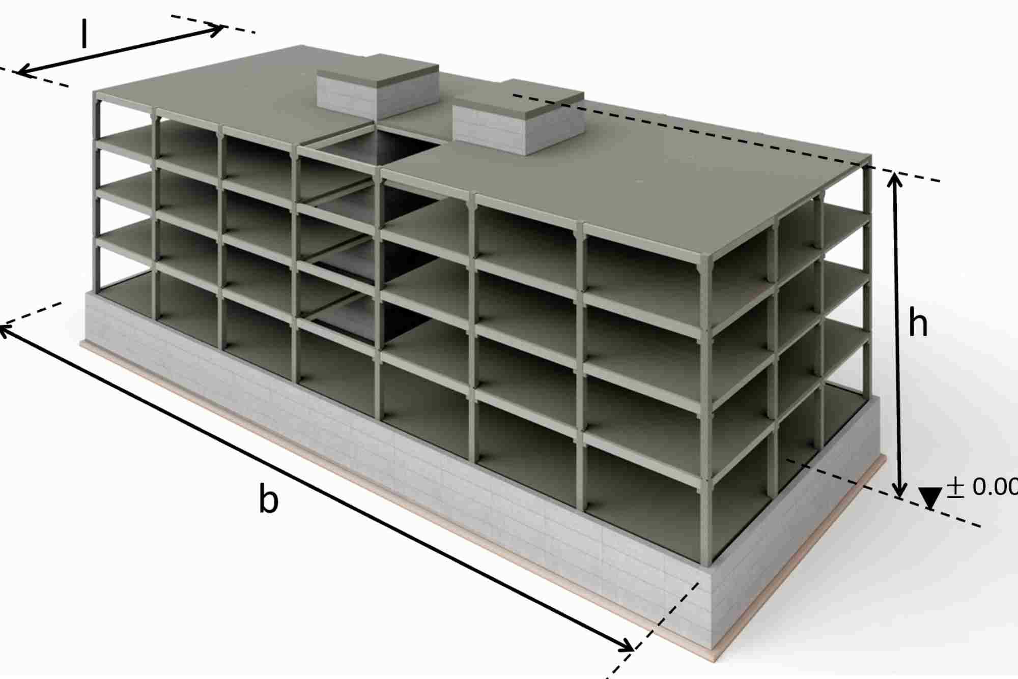
Determine Structure Geometry
Wind load is distributed based on the exposed surface area of the steel structure. For a rectangular building, calculate the area of each wall and roof exposed to wind.
- Larger surface areas increase total load
- Sloped roofs may have different coefficients on each side
- Openings like windows or vents can change wind pressure distribution
Accurate geometry ensures that each member, from beams to columns, can withstand the applied loads.
Apply Shape and Height Factors
Tall structures or irregular shapes respond differently to wind. Shape factors (also called pressure coefficients) account for the building profile, while height factors adjust for wind speed variation with altitude.
- Tall structures experience higher wind speeds at the top
- Concave or convex surfaces may increase or reduce pressure
- ASCE 7 provides charts for common building shapes and heights
These adjustments are crucial for preventing underestimation of wind forces.
Calculate Wind Load on Each Member
Once total wind pressure is known, distribute it to individual steel members. Columns, beams, trusses, and braces may carry different portions of the load depending on layout and connections.
- Columns bear lateral load transfer to the foundation
- Roof purlins resist wind uplift
- Bracing provides stability against swaying
Structural analysis software can model these forces to ensure even distribution.
Factor in Safety Margins
Engineering codes require safety factors to account for uncertainties in wind speed, material properties, and construction variations. Typical safety factors range from 1.3 to 1.6. This ensures the structure remains safe even under extreme events.
Verify with Local Codes
Before finalizing calculations, verify compliance with local building codes. Codes may specify:
- Maximum allowable deflections
- Minimum member sizes
- Connection requirements
Compliance avoids legal issues and guarantees structural performance under local wind conditions.
Practical Example
Consider a steel warehouse measuring 30 meters long, 20 meters wide, and 8 meters high in a coastal area with a basic wind speed of 50 m/s.
- Exposure Category: D (open coastal terrain)
- Shape Factor: 1.3 for vertical walls, 0.9 for roof
- Design Pressure:
P = 0.613 × 50² × 1.3 × 1 × 1 = 1992 kPa
- Total Wind Force: Multiply P by the exposed area to get force on each wall and roof.
- Member Design: Use calculated forces to size columns, beams, and bracing.
This simplified example shows the logic; detailed design requires software and code references for exact member sizing.
Common Mistakes to Avoid
- Ignoring exposure category or terrain roughness
- Using outdated wind speed data
- Overlooking roof uplift and openings
- Applying wind load only on one side of the structure
- Neglecting safety factors or local code requirements
Correcting these mistakes early prevents costly redesigns and safety hazards.
Calculating wind load on steel structure is essential for safety, durability, and regulatory compliance. By following the step-by-step method outlined above—determining wind speed, exposure, design pressure, geometry, and member distribution—you can ensure your steel structure withstands even extreme wind conditions. Modern software tools simplify calculations, but understanding the underlying principles is crucial for informed design decisions.
Accurate wind load calculations protect lives, reduce maintenance costs, and enhance structural performance. If you are planning a steel construction project, make sure your engineer applies these methods carefully.
For professional guidance on designing steel structures to resist wind loads, contact a certified structural engineer today and secure your project against extreme weather.
Looking to manage your finances smarter? financer.ae offers expert tips, tools, and insights to help you save, invest, and plan for a secure future. From budgeting guides to investment strategies, we make financial planning simple, efficient, and tailored to your goals—empowering you to take control of your money today.
FAQ
What is wind load in a steel structure?
Wind load is the force exerted by wind on a steel structure, depending on speed, terrain, and shape. It affects stability and safety.
How do you calculate wind pressure?
Wind pressure is calculated using the formula P = 0.613 × V² × Cf × Ce × Cd, which considers velocity, shape, exposure, and dynamic factors.
What factors affect wind load on steel structures?
Wind load depends on wind speed, building height, exposure category, structural shape, and surface area.
Why is wind load important for steel buildings?
Steel buildings are strong but flexible. Wind load ensures columns, beams, and braces are designed to resist swaying and uplift.
Which code is used for wind load calculation?
Common codes include ASCE 7, Eurocode, and IS 875 Part 3, providing guidelines for wind pressure, exposure, and structural design.