




Introduction
Learning How to Calculate Wire Feed Speed in MIG Welding is essential for producing stable arcs, strong welds, and consistent bead profiles. Wire feed speed, often called WFS, controls how quickly welding wire enters the arc. It also has a major effect on welding current when using constant-voltage MIG equipment.
The correct wire feed speed depends on several factors. These include wire diameter, material thickness, wire type, shielding gas, welding position, and machine settings. Therefore, there is no single wire feed speed that works for every MIG welding job.
Understanding the relationship between wire feed speed and amperage makes setup much easier. It also helps welders troubleshoot problems such as excessive spatter, poor penetration, burnback, and an unstable arc. With the right approach, you can calculate a useful starting setting and then fine-tune it through testing.
Understanding Wire Feed Speed in MIG Welding
Wire feed speed refers to the speed at which the welding machine feeds consumable wire toward the contact tip. It is commonly measured in inches per minute, or IPM. Some welding equipment may display the setting using metres per minute.
In MIG welding, wire feed speed affects the amount of metal deposited into the weld. Increasing the speed generally increases welding current because more wire must melt within the arc. Lowering the speed generally reduces current and deposition.
This relationship is particularly important with constant-voltage MIG machines. The voltage primarily influences arc length, while wire feed speed strongly influences amperage. Both settings must work together to create a stable arc.


When learning How to Calculate Wire Feed Speed in MIG Welding, remember that wire feed speed should not be selected independently. It must match the wire diameter, material, welding process, and recommended operating range.
Why Correct Wire Feed Speed Matters
Correct wire feed speed helps create a smooth and controlled welding arc. When the setting is appropriate, the wire melts consistently and transfers metal into the weld pool.
If the wire feed speed is too high, the welder may experience excessive spatter. The wire can also push aggressively into the weld pool. This creates a harsh arc and may produce an irregular bead.
If the wire feed speed is too low, the arc can become unstable. The wire may burn back toward the contact tip. The weld can also become narrow or lack sufficient deposition.
Therefore, How to Calculate Wire Feed Speed in MIG Welding is not simply about finding one mathematical number. It is about establishing a suitable starting point and adjusting the setting according to actual welding conditions.
The Main Factors That Affect Wire Feed Speed
Wire diameter is one of the most important factors. Thicker wire generally requires different feed rates and current levels than thinner wire. Common MIG wire diameters include 0.023, 0.030, 0.035, and 0.045 inches.
Material thickness also affects the required setting. Thin sheet metal usually needs lower heat input. Thicker steel may require greater deposition and penetration.
The wire material matters as well. Solid steel wire, stainless steel wire, and aluminium wire have different welding characteristics. Their recommended settings can vary significantly.
Shielding gas also influences the arc. A common gas mixture for mild steel is argon and carbon dioxide. Pure carbon dioxide produces different arc characteristics and may require different settings.
Welding position is another consideration. Flat welding can usually tolerate higher deposition rates. Vertical or overhead welding often requires more controlled settings.
How to Calculate Wire Feed Speed in MIG Welding
There is no universal equation that produces an exact WFS for every MIG welding application. Manufacturers normally provide recommended settings based on wire diameter, material, gas, and welding current.
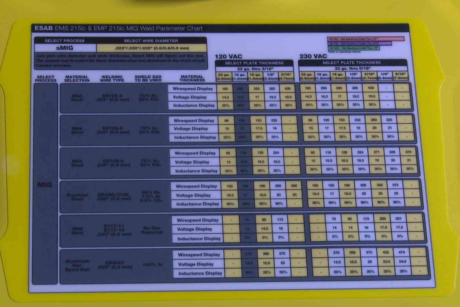
A practical method begins with the desired welding current. You then select the wire diameter and consult the manufacturer’s welding chart. The chart provides a recommended wire feed speed and voltage range.
For example, suppose you are welding mild steel with solid wire. You select a suitable wire diameter for the material thickness. You then identify the recommended amperage range for that wire.
The corresponding wire feed speed becomes your starting point. After that, make a test weld and observe the arc. Adjust the WFS gradually until the arc becomes smooth and the weld profile looks appropriate.
This approach is more reliable than applying one fixed formula to every welding situation.
Relationship Between Amperage and Wire Feed Speed
Understanding amperage is central to How to Calculate Wire Feed Speed in MIG Welding. With many constant-voltage MIG systems, increasing WFS increases amperage. This happens because more wire enters the arc and must be melted.
However, the exact amperage-to-WFS relationship depends on wire type, diameter, electrode extension, polarity, and machine characteristics.
For this reason, experienced welders often use WFS as the primary current-control setting. Voltage is then adjusted to establish the appropriate arc length.
A higher WFS generally produces greater deposition. It can also increase penetration when the other settings are appropriate. However, excessive WFS can overwhelm the arc and create poor weld quality.
Using Welding Charts for Accurate Settings
The easiest way to determine WFS is often the manufacturer’s welding parameter chart. These charts are designed around specific consumables and equipment.
A typical chart may provide material thickness, wire diameter, shielding gas, voltage, amperage, and WFS recommendations. Start within the manufacturer’s recommended range instead of guessing.
Machine manuals are particularly useful when working with synergic or programmable MIG welders. Modern machines may automatically coordinate WFS and voltage based on the selected material and wire.
Even when a machine provides automatic settings, understanding How to Calculate Wire Feed Speed in MIG Welding remains valuable. It allows you to recognize incorrect settings and make informed adjustments.
Calculating a Starting Setting
Consider a situation where you need to weld a moderate-thickness mild steel component. You choose solid steel wire because it suits the material and equipment.
First, identify the recommended wire diameter. Next, check the wire manufacturer’s or welding machine manufacturer’s parameter chart. Find the recommended current range for your material thickness.
The chart may then provide a corresponding WFS range. Select a middle value as your starting point. Set the recommended voltage and shielding gas flow rate as well.
Make a short test weld on scrap material. Listen to the arc and inspect the resulting bead. If necessary, adjust WFS in small increments.
This practical process is usually more accurate than attempting to calculate an exact number from amperage alone.
How Wire Diameter Changes the Calculation
Wire diameter has a direct influence on WFS. A smaller wire can generally be used at lower deposition rates. Larger wire can carry more current and deposit more metal.
For example, 0.023-inch wire is commonly selected for thinner materials. It can provide better control when working with light-gauge steel.
A 0.030-inch or 0.035-inch wire may be more suitable for general fabrication. Larger diameters can be useful for heavier materials and higher deposition requirements.
Consequently, How to Calculate Wire Feed Speed in MIG Welding should always begin with selecting the correct wire diameter. Choosing the wire first makes it easier to identify an appropriate WFS range.
Signs That Wire Feed Speed Is Too High
An excessively high WFS can produce several recognizable problems. The wire may appear to push into the workpiece instead of melting smoothly.
You may notice a harsh, forceful arc accompanied by excessive spatter. The weld bead can become tall and irregular. In some cases, the machine may produce frequent arc interruptions.
High WFS can also create excessive deposition. This may result in an unnecessarily large weld that does not improve joint strength.
If these symptoms appear, reduce WFS gradually. At the same time, verify that voltage remains appropriate for the selected wire and process.
Signs That Wire Feed Speed Is Too Low
Low WFS produces different symptoms. The arc may become long and inconsistent when the voltage remains unchanged.
Burnback can occur when the wire melts faster than it is being supplied. This may cause the wire to fuse to the contact tip.
The resulting weld may also have insufficient reinforcement or deposition. Inconsistent feeding can make the bead difficult to control.
Increasing WFS gradually can restore arc stability. However, the voltage should also be checked because WFS and voltage must remain properly balanced.
How Voltage Works With Wire Feed Speed
Wire feed speed and voltage perform different but connected functions. WFS primarily controls the amount of wire entering the arc. Voltage strongly influences arc length and arc characteristics.
Increasing WFS without adjusting voltage can produce an excessively short arc. Reducing WFS while leaving voltage high can create an overly long arc.
Therefore, How to Calculate Wire Feed Speed in MIG Welding should always include consideration of voltage. The goal is not simply to achieve a specific feed speed.
Instead, the goal is to establish a stable arc with suitable penetration, bead shape, deposition, and heat input.
Practical Tips for Better MIG Settings
Always start with the manufacturer’s recommended parameters. These settings provide a safer and more reliable foundation.
Keep the contact-tip-to-work distance consistent. Changes in electrode extension can influence resistance and welding characteristics.
Maintain proper gun angle and travel speed. Even perfect WFS cannot compensate for poor welding technique.
Clean the base metal before welding. Rust, oil, paint, and contamination can interfere with arc stability and weld quality.
Also check the wire feeding system. Worn drive rolls, incorrect tension, blocked liners, or a damaged contact tip can create symptoms that look like incorrect WFS.
Common Mistakes When Setting Wire Feed Speed
One common mistake is assuming that WFS has the same meaning on every welding machine. Different machines can have different calibration and parameter systems.
Another mistake is changing WFS dramatically. Small adjustments usually make troubleshooting easier because you can clearly identify their effect.
Some welders also focus only on amperage. However, wire diameter, voltage, gas, travel speed, and material thickness must be considered together.
Finally, avoid relying entirely on appearance. A weld can look acceptable while having poor penetration or other quality problems. Proper welding procedures and inspection remain important.
A Simple Approach to Finding the Correct Setting
When How to Calculate Wire Feed Speed in MIG Welding is the goal, start with the basics. Identify your material, thickness, wire type, wire diameter, and shielding gas.
Then consult the welding machine or consumable manufacturer’s recommended parameters. Choose a suitable starting WFS and voltage combination.
Make a test weld on similar material. Listen to the arc and inspect the bead profile. If the arc feels too aggressive, reduce WFS or review the voltage setting.
If the arc feels weak or the wire burns back, increase WFS gradually. Make only one adjustment at a time whenever possible.
This method helps you develop repeatable welding settings for future projects.
Understanding How to Calculate WIP is important for tracking production costs and measuring business performance. Work in Progress (WIP) helps businesses determine the value of unfinished goods at a specific time. Accurate WIP calculations support better budgeting, inventory management, and financial reporting.
Frequently Asked Questions
What is wire feed speed in MIG welding?
Wire feed speed is the rate at which welding wire travels from the welding gun into the arc. It is usually measured in inches per minute.
How do I calculate wire feed speed for MIG welding?
The most reliable method is to use the manufacturer’s welding chart. Select the wire diameter, material thickness, wire type, and shielding gas. Then use the recommended WFS range as your starting point.
Does increasing wire feed speed increase amperage?
Generally, yes. On many constant-voltage MIG systems, increasing WFS increases welding current because more wire must be melted.
What happens if MIG wire feed speed is too high?
The arc can become harsh and unstable. Excessive spatter, poor bead shape, and excessive deposition may occur.
What happens if wire feed speed is too low?
The arc may become unstable, and burnback can occur. The weld may also have inadequate deposition.
Is wire feed speed the same as amperage?
No. They are closely related but are not the same measurement. WFS describes wire travel speed, while amperage measures electrical current.
Conclusion
Understanding How to Calculate Wire Feed Speed in MIG Welding helps welders create consistent and reliable welds. The correct setting depends on wire diameter, material thickness, wire type, shielding gas, voltage, and welding position.
Related Reading: Is Investing in Real Estate a Good Idea?
Related Reading: How to Calculate Words per Minute Typing
Related Reading: Where NRI Can Invest in India?